Zoom Conferencing System Design
Who hasn’t used Zoom or Microsoft teams or WebEx or some sort of video conferencing platform by now! Even classes are being conducted on Zoom these days. If you are reading this I am sure you are curious about how it works or are preparing for your next big interview! So read on and by the end of this article, you will be able to successfully design a video conferencing system.
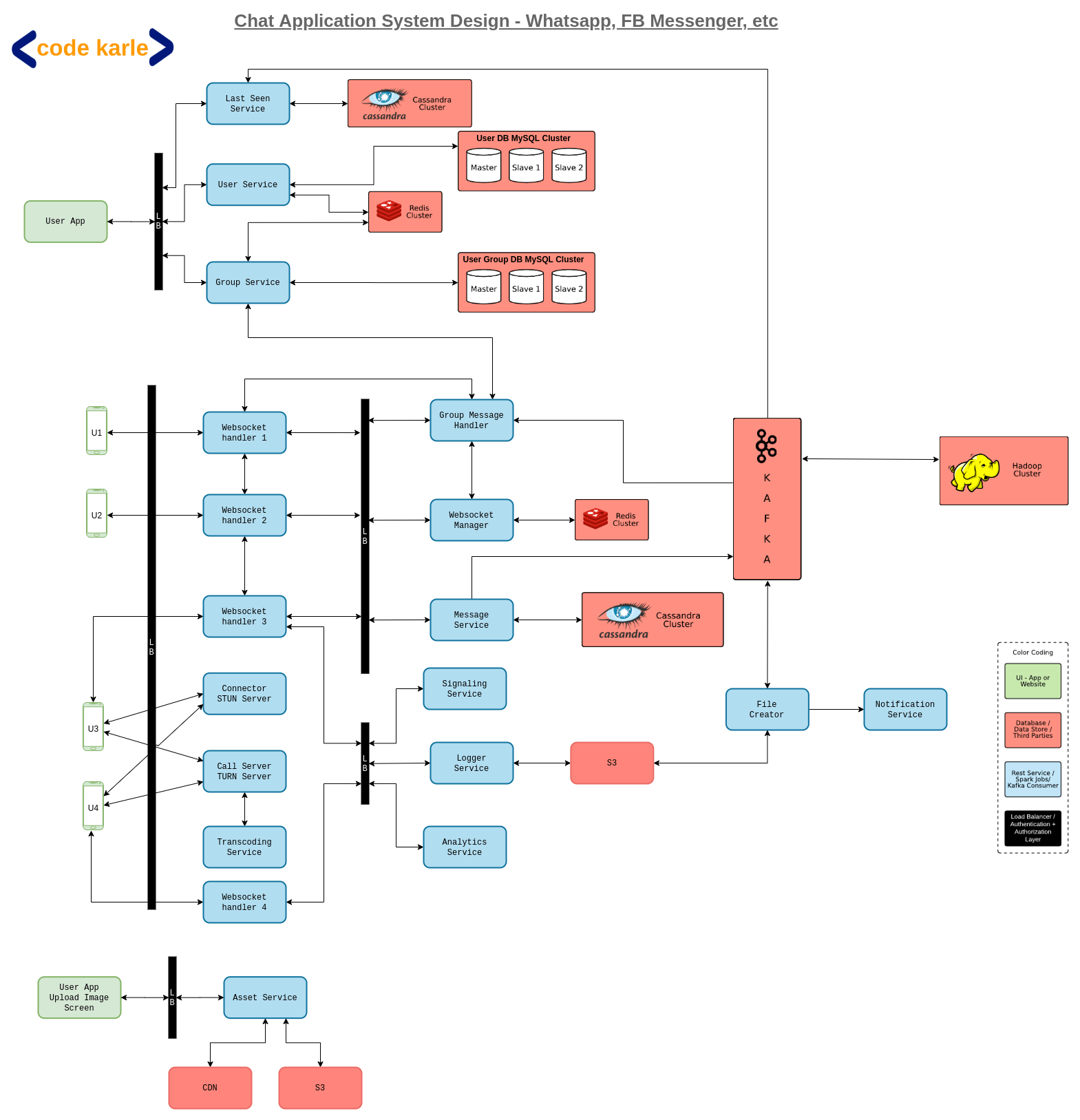
Just a disclaimer - the solution we will be discussing is heavily based on the solution we discussed for WhatsApp system design, so it is highly suggested you go through that first.
First things first, let’s lock down the requirements.
Functional Requirements
- The system must support 1-to-1 calls
- The system must support group calls
- Calls can be audio or video or screen sharing
- Should offer a call recording feature
Note: Screen share will be an extension of video call itself, only in case of video call the source of the video is the camera, whereas in screen share source of the video will be the screen.
Non Functional Requirements
- Should be super fast - low latency is not enough
- High availability
- Data loss is OK
Yes, data loss is ok. This should give you a hint about what we are going to discuss next. Let us talk about Transport Layer protocols.
TCP? UDP? Both!!
As we know, any client-server communication will usually happen over HTTP or HTTPS channels, In case the communication is bidirectional we will use web socket protocols. In these cases usually, the connection is formed after a three-way TCP handshake i.e. client sends a connection request to the server, the server responds with an acknowledgment, the client responds back with an acknowledgment of the acknowledgment and a connection is formed. This 3-step process is known as a three-way TCP handshake.
Now that the connection is established, how does the data transfer happen? A point to remember here is that TCP is a lossless protocol. That means the data packets cannot go missing. TCP ensures this by receiving an acknowledgment from the receiver for every data packet it receives. Until the sender receives the acknowledgment for a data packet it will keep sending the data packet again and again
Another thing TCP does is confession control i.e. every time the network gets choked due to high traffic, it will delay sending some data packets so as to not overwhelm the network. So including the time taken for a handshake, acknowledgments from the server, resending of the same packets, and delay introduced because of congestion control, there is a lot of overhead involved to maintain data accuracy which is not even a priority for us.
This means we need to look at alternatives for TCP which involve less overhead. Here we will use something called UDP which is another Transport Layer protocol but it is different from TCP in that it is a lossy protocol.
Unlike TCP, in UDP there is no requirement to form a connection. As long as the devices are aware of each other’s public IP address, they can talk via peer to peer connection. Also, as mentioned above, UDP is a lossy protocol, which means there is no concept of acknowledgment in UDP. If the sender sends packets P1, P2, P3, and P4 but the receiver only receives packets P1, P3, and P4, the sender won’t bother sending P2 again i.e. there might be some data loss.
So using UDP means less congestion since extra traffic is avoided and one packet is sent only once, less data transfer since we can avoid all those acknowledgments and lesser header size. So though the data reaching the receiver might not be perfect, it will reach a lot faster.
But for our system using just UDP will not be enough. We will be using a combination of TCP and UDP. All the API calls, all communication between components, etc will happen over TCP but all video transfer will happen over UDP.
Connector? Call server?
If you haven’t gone through the WhatsApp system design tutorial yet, now is a good time because the components we will be using here are discussed in that article in much greater detail. Now let us understand exactly how the whole video call will take place with an example. Say U1 wants to initiate a call with U2 but U2 is offline. In this case, you can decide how to let U1 know about U2 being unavailable. But when U2 is online, a web socket handler will send a message to U2 that U1 wishes to call them and if they want to accept. Whatever U2 decides will be communicated to U1 using the same route. Now this whole connection between U1 and U2 via web socket handler is a TCP connection. But for the video call, we need to move to a UDP connection. So how do we establish a UDP connection between U1 and U2?
Well technically UDP is a connectionless protocol, as the public IP addresses of both parties is the only thing required for this mode of communication. So when we say “establishing a UDP connection”, we mean sharing the information to set up this UDP connection i.e. each other's public IP address. This is where a connector comes in. A connector’s job is to identify a user’s public IP address information. So U1 will get its public IP from the connector, U2 will get its public IP from the connector and they will share this information via web socket handler. Once they have each other’s public IP address they can start sharing video messages.
But why do we even go through the whole process just to get the public IP address of the involved parties? Because for communication over UDP you need a public IP address. Now if both the users were on IPv6 it wouldn’t be a problem because they would already have a public IP address and can share it. But a huge number of devices are still on IPv4. And in IPv4 most of the devices will be connected to their router with a private IP address, and probably their router will also be connected to a series of routers with a private IP address which finally will be connected to the ISP router which will have a public IP address. So ISPs public IP address along with whichever port U1 is connected on will become U1’s public IP address that will be communicated to U2 via a connector.
Refer to this diagram, we will understand with this example of how the private IP address will be used to find the public IP address of the device. Suppose we have D1, D2, and D2 connected to a series of routers which in the end have a router with a public IP address and a NAT in the same layer. Let’s say the public IP address of this router is A.B.C.D and devices D1, D2 and D3 are connected at ports P1, P2, and P3 respectively. So when D1 connects to our connector, as far as the connector is concerned, a request is coming from A.B.C.D: P1 which becomes the public address of D1 and it will respond to D1 with public IP address A.B.C.D: P1. In this manner, U1 and U2 will get three public IPs from the connector and then communicate it to each other using the Web socket handler.
Now at this stage, we haven’t considered some very common and expected scenarios. Suppose U1 is on 5G network and can support HD videos but U2 is on 2G network and HD videos will considerably slow down the communication. So it makes no sense for U2 to receive videos in HD format. So how will U1 and U2 sort out these minor details like device resolution, network bandwidth, etc? Along with sharing their public IPs, U1 and U2 will also share these other attributes like bandwidth they are on, codecs, number of pixels the devices can support, etc, and decide on a configuration that supports the device with minimum capability in each category. For example, if U2 is on a lower bandwidth they will support a lower bandwidth, if U1 is on a device with the low resolution they will support a lower resolution etc. These attributes are also communicated via the web socket handler. After this, the actual call will begin which will just be a stream of data packets flowing between the two IP addresses. At this point, each device will act as a sender as well as a receiver and will be smart enough to render the data they receive.
Now there is one more thing that can go wrong here. Remember that Router + NAT layer in our previous diagram? Usually, that layer also has a Firewall. And some Firewalls don’t allow UDP traffic to pass. In this case, the communication will have to move to a TCP connection. Also, we have something called a symmetric NAT. If we have a symmetric NAT in this layer, it will allow only the connector to talk to the port connected to the device. Now say U1 was device D1 and U2 was device D2, when U1 tried to connect to P2 the firewall would block that connection saying only the connector can communicate with this port. Did our whole solution just go down the drain?
Well not really. Here we will introduce something called Call Server between U1 and U2. Call servers can do the job of a connector as well as facilitate data transfer. Now the ports for U1 and U2 will be identified by the call server and from then on it will start acting as an intermediate between U1 and U2. U1 will send its data to be forwarded to U2 and U2 will communicate with U1 in a similar fashion. This whole process or protocol is known as WebRTC.
The handshaking that was done by the web socket handler is known as Signaling. Our connector in WebRTC terminology is known as the STUN Server and the call server is known as the TURN Server.Group video calls
Ok so now we know how 1-to-1 video calls work. Are group video calls the same? Well Yes and No. Members of a group video call will interact in a similar manner but it will follow a more hybrid approach.

The group will be classified based on size. Let’s say we have a threshold of 5. Now in the above example of a video call of four people, If U1, U2, U3, and U4 are connected through peer to peer network, U1 will send the same data packets to U2, U3, and U4 when it is talking, which is totally fine for a group of 4 people. But what if it is a full-blown conference with 100 odd people? Let’s look at the math here. If there are N members in a group, each member’s bandwidth requirement will be increased N-1 times because it will be sending to and receiving from N-1 People in the group call.
And larger the value of N, bigger the problem. In such a case we will follow the Call server approach so each user will be sending to receiving from only the call server. This might put some load on the call server but that is easily manageable by scaling the hardware as per requirement. User’s bandwidth is something we can not control so our priority will be to optimize the use of users’ bandwidth utilization.
Now, remember that 5 people threshold? How did we reach number 5? Well, this will not be a static value, It will be calculated dynamically based on the geographic location of users, network bandwidth, availability, etc. Let’s say some employees who are connected to their office private network and sitting at their desks are connected on a video call. Since they are located very closely together and on the same network latency will be very low and we can maybe support even 10 employees on point to point connection. But if the users were located across different countries supporting even 3 on a peer to peer connection might be difficult.
Call Recording
Also, remember the call recording feature? That is another reason to go with the call server approach. If we go with the p-to-p model, the complete call will not be present in a single location anywhere and recording will become difficult. So if a call has to be recorded it will have to be routed via the call server.
Is it secure?
Now some of you might raise the question of security. Is it secure to transmit so much data in a peer to peer manner over an open network? Yes, it is. The first handshake that happened over the signaling server? The devices at that time will also share private keys along with their public IP address. And every time the data packet is shared in a UDP manner, it will be encrypted on the sender’s side and decrypted on the receiver’s side using this key.
System Architecture
Now before we get on with the architecture, let us understand that every video calling platform out there also supports a chat functionality to go with it. So we are going to extend the same system that we designed in the WhatsApp system design tutorial to be able to support video calls.
Suppose U1 wants to initiate a call with U2. All users will be connected to Web Socket Handlers, which will keep open connections with all online users. And web socket handlers will further be connected to a Web Socket Manager which will keep track of which web socket handler is connected to which user. Web socket managers will use a Redis to cache this data and make it fault-tolerant. Now when U1 tries to connect with U2, it will call the web socket handler which in turn calls the Signaling Service which will initiate the call between two parties. It will also perform some checks to confirm if the call should be made or not. For example, say in a Facebook video call you should not be able to initiate a call if the other person is not your friend. Signaling service will use a User Service which is a repo of all users to support such checks. Now signaling service will talk to the web socket handler of U2 to see if U2 wants to accept the call or not. In case the call is accepted signaling service communicates that to U1. At this point, both U1 and U2 talk to the connector (STUN server) to find each other’s IP address and there is another handshake to decide on the configuration for the call. After this, a peer to peer connection will be established between them and they can start the video call. Now please remember that the video here will be shared in very small chunks of a few milliseconds each to ensure a seamless experience. If for some reason a p-to-p connection is not formed, the communication will take place through the call server (TURN server).
Now, remember that second handshake where we decided on the bandwidth requirement for the call? I am sure you have all experienced this, but bandwidth is not a constant, it fluctuates more often than not. So let’s assume U2’s network speed dropped in the middle of the call and U2 wants to support a lower resolution and bandwidth. U2 will communicate this to U1 via singling service and a new configuration will be decided.
Every time such a change happens, it will affect the user experience, which makes it an important data point for us. So every time a configuration change happens, signaling service will fire an event to Kafka. Some analytics can also be performed on the data shared by devices like geographical location, change in user’s location, supported resolution, user’s device, etc. This information will be sent by the device via a web socket handler to an analytics service that will take these inputs and send them to Kafka.
Now let’s go back to that recording feature. As discussed before, if we want the call to be recorded the call must be routed through the call server. When U1 sends a data packet to the call server, it is forwarded to U2 and also to a logger service. Logger service aggregates these data chunks and sends them to a distributed file system to be stored against a meeting id. The distributed system will only hold this data for as long as the call is on. Once the call is disconnected signaling service will know through the web socket handler and fire an event to Kafka. The next component that comes into play here is a File creator (you can also call it an archiving service).
When Kafka receives an event that call has been disconnected, File creator will listen to it, fetch all the chunks for data for that meeting id from the distributed file system and compile them into a video. This video will then be stored in a permanent data store like S3. Once this file is created the Notification Center will send out a notification to all involved users that this file is available for them to view.
Again, the next question is, how will this work for a group video call? This is where it gets a little tricky. In a group call, we will need to do some transcoding before sending the data packets to various users. It is suggested that you guys check out the Netflix system design tutorial where we have discussed Transcoding in detail but here is the basic gist - Since our users will be connecting from different kinds of devices, they will be supporting different formats, and we need to be able to send them the data in that particular format, which is where Transcoding comes in. That means we will convert the original video to support multiple formats and a variety of bandwidths, bitrates, etc. - Now let’s say, U1 is sending a video to U2 and U3, and user U3 is connected to a network with poor speed and wants a low definition call. This message will reach the call server. The call server will know that U2 can support HD videos and directly send the high-quality video to U2. It will also know that U3 needs an SD video and convert the video to a lower definition. For this, it will talk to the Transcoding Service to convert the video to SD format and send it to U3. Now, remember that transcoding is a one-way operation i.e. an HD video can be converted to that of lower definition but not the other way round. So when U3 sends a video of its own, the call server will know that it cannot be transcoded to a video of superior quality and skip the call to the transcoding service and send the data packet to U1 and U2 directly. Also, this information will be stored by the call server which will use a Redis to cache it.
Now we will come to the Analytics part of our solution. Data is the new oil after all, and with all the events we have been firing to Kafka, we can use this data to make important business decisions. There is something called an Analytics Engine that will read all the Kafka events and generate reports. These could be simpler reports based on time series data like how many people are using the system, how often people are getting dropped off etc. Or we could dump the whole data into a Hadoop cluster and perform some more complex analytics.
How intelligent is the client?
This is the next big question. Exactly what operations can the client perform independently? Going back to the U1-U2 video call, we know that our clients are smart enough to know their limitations like bandwidth, bitrate, resolution, etc, and communicate to the other party and come up with a configuration for the call that works for both of them. Now let’s say while U1 and U2 are in a peer to peer call, U1’s public IP keeps changing or the call keeps getting dropped. In such a case our clients will be smart enough to mutually decide that their p-to-p connection is not working and they need to move to the call server model. This will all happen at run time. Also, this switch won’t necessarily happen at the same time. U1 could be sending messages to U2 directly and U2 could be sent through the call server. Even in a group call, the same flow will apply.
How about a live broadcast?
Yes, we can extend this system to work in case of a live broadcast. Suppose some huge sporting event is taking place that millions of people want to watch, let’s take an example of the India vs Pakistan cricket World Cup Final. Now, you can be sure that millions of people want to watch the live stream for this event. How can we scale our system to support that?

For any such events, the stream would be coming from multiple cameras and audio devices. We can safely assume there will be an input manager which will decide from which cameras and audio devices it wants to stream the data and accordingly combine the elements to form the video. Then it will communicate this video to a call server to share it with the wider audience. This call server will now send the request to multiple Transcoders to convert this video stream into multiple formats suitable for various devices and network requirements. If the hardware is good enough, we can transcode the packets at real-time. All we need is multiple transcoders based on how many data formats we need. Now the second set of call servers will receive the transcoded output of a specific format and will forward this formatted output to a third set of call servers. Now again, this is a live broadcast that millions of people are watching, we need a CDN like a setup to cater to all of them. So this third layer of call servers will be spread across the world and will then distribute the data to all users with the lowest possible latency. This kind of takes inspiration from how Netflix is implemented so make sure to go through that tutorial as well.
Now, remember the second layer of call servers received output of only specific formats i.e. even the third layer of call servers will have the output of a single data format and will cater to users of only that requirement. Also, we will try to keep this third level of call servers as close to the user as possible to reduce the latency.
And with that, we have successfully designed a system like a Zoom or Microsoft Teams and extended it to a system that supports Live broadcasts as well. Send in your thoughts on our youtube video!